- 您现在的位置:买卖IC网 > Sheet目录325 > FAN73933MX (Fairchild Semiconductor)IC GATE DVR HALF BRIDGE 14-SOIC
�� �
�
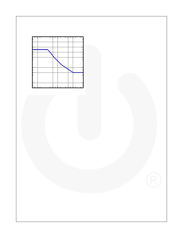
�The� FAN73933� has� a� negative� V� S� transient� performance�
�curve,� as� shown� in� Figure� 43.�
�-100�
�-90�
�-80�
�-70�
�-60�
�-50�
�-40�
�-30�
�-20�
�-10�
�Placement� of� Components�
�The� recommended� selection� of� component� is� as� follows:�
�Place� a� bypass� capacitor� between� the� V� DD� and� V� SS�
�pins.� A� ceramic� 1μF� capacitor� is� suitable� for� most�
�applications.� This� component� should� be� placed� as�
�close� as� possible� to� the� pins� to� reduce� parasitic� ele-�
�ments.�
�The� bypass� capacitor� from� V� CC� to� COM� supports� both�
�the� low-side� driver� and� bootstrap� capacitor� recharge.�
�A� value� at� least� ten� times� higher� than� the� bootstrap�
�capacitor� is� recommended.�
�The� bootstrap� resistor,� R� BOOT� ,� must� be� considered� in�
�sizing� the� bootstrap� resistance� and� the� current� devel-�
�oped� during� initial� bootstrap� charge.� If� the� resistor� is�
�needed� in� series� with� the� bootstrap� diode,� verify� that�
�V� B� does� not� fall� below� COM� (ground).� Recommended�
�use� is� typically� 5� ~� 10� Ω,� which� increases� the� V� BS� time�
�constant.� If� the� votage� drop� of� the� bootstrap� resistor�
�0�
�0�
�100�
�200�
�300�
�400�
�500�
�600�
�700�
�800�
�900� 1000�
�and� diode� is� too� high� or� the� circuit� topology� does� not�
�allow� a� sufficient� charging� time,� a� fast� recovery� or�
�Pulse� Width� [ns]�
�Figure� 43.� Negative� V� S� Transient� Chracteristic�
�Even� though� the� FAN73933� has� been� shown� able� to�
�handle� these� negative� V� S� tranient� conditions,� it� is�
�strongly� recommended� that� the� circuit� designer� limit� the�
�negative� V� S� transient� as� much� as� possible� by� careful�
�PCB� layout� to� minimize� the� value� of� parasitic� elements�
�and� component� use.� The� amplitude� of� negative� V� S� volt-�
�age� is� proportional� to� the� parasitic� inductances� and� the�
�turn-off� speed,� di/dt,� of� the� switching� device.�
�General� Guidelines�
�Printed� Circuit� Board� Layout�
�The� layout� recommended� for� minimized� parasitic� ele-�
�ments� is� as� follows:�
�Direct� tracks� between� switches� with� no� loops� or� devia-�
�tion.�
�Avoid� interconnect� links.� These� can� add� significant�
�inductance.�
�Reduce� the� effect� of� lead-inductance� by� lowering�
�package� height� above� the� PCB.�
�Consider� co-locating� both� power� switches� to� reduce�
�track� length.�
�To� minimize� noise� coupling,� the� ground� plane� should�
�not� be� placed� under� or� near� the� high-voltage� floating�
�side.�
�To� reduce� the� EM� coupling� and� improve� the� power�
�switch� turn-on/off� performance,� the� gate� drive� loops�
�must� be� reduced� as� much� as� possible.�
�?� 2009� Fairchild� Semiconductor� Corporation�
�FAN73933� ?� Rev.� 1.0.0�
�15�
�ultra-fast� recovery� diode� can� be� used.�
�The� bootstrap� capacitor,� C� BOOT� ,� uses� a� low-ESR�
�capacitor,� such� as� a� ceramic� capacitor.�
�It� is� stongly� recommended� that� the� placement� of� compo-�
�nents� is� as� follows:�
�Place� components� tied� to� the� floating� voltage� pins� (V� B�
�and� V� S� )� near� the� respective� high-voltage� portions� of�
�the� device� and� the� FAN73933.� NC� (not� connected)�
�pins� in� this� package� maximize� the� distance� between�
�the� high-voltage� and� low-voltage� pins� (see� Figure� 3.).�
�Place� and� route� for� bypass� capacitors� and� gate� resis-�
�tors� as� close� as� possible� to� gate� drive� IC.�
�Locate� the� bootstrap� diode,� D� BOOT� ,� as� close� as� possi-�
�ble� to� bootstrap� capacitor,� C� BOOT� .�
�The� bootstrap� diode� must� use� a� lower� forward� voltage�
�drop� and� minimal� switching� time� as� soon� as� possible�
�for� fast� recovery� or� ultra-fast� diode.�
�www.fairchildsemi.com�
�发布紧急采购,3分钟左右您将得到回复。
相关PDF资料
FAN7393AMX
IC GATE DVR HALF BRIDGE 14SOIC
FAN7842MX
IC DRIVER HIGH/LOW GATE 8-SOP
FAN7888MX
IC GATE DRIVER HALF BRIDG 20SOIC
FDA215S
IC DRIVER MOSFT DUAL PHOTO 8-SMD
FDS1212
SHELF FOLD DOWN 12X12" BEIGE
FDS1818
SHELF FOLD DOWN 18X18" BEIGE
FFSD-17-01-N
CONN SOCKET 34POS IDC .05"
FI-DP42CL1 PLUG
PLUG 42POS COAX DISCRETE WIRE
相关代理商/技术参数
FAN7393A
制造商:FAIRCHILD 制造商全称:Fairchild Semiconductor 功能描述:Half-Bridge Gate Drive IC
FAN7393A_12
制造商:FAIRCHILD 制造商全称:Fairchild Semiconductor 功能描述:Half-Bridge Gate Drive IC
FAN7393AM
功能描述:功率驱动器IC Half Bridge Gate Driver RoHS:否 制造商:Micrel 产品:MOSFET Gate Drivers 类型:Low Cost High or Low Side MOSFET Driver 上升时间: 下降时间: 电源电压-最大:30 V 电源电压-最小:2.75 V 电源电流: 最大功率耗散: 最大工作温度:+ 85 C 安装风格:SMD/SMT 封装 / 箱体:SOIC-8 封装:Tube
FAN7393AMX
功能描述:功率驱动器IC Half Bridge Gate Driver
RoHS:否 制造商:Micrel 产品:MOSFET Gate Drivers 类型:Low Cost High or Low Side MOSFET Driver 上升时间: 下降时间: 电源电压-最大:30 V 电源电压-最小:2.75 V 电源电流: 最大功率耗散: 最大工作温度:+ 85 C 安装风格:SMD/SMT 封装 / 箱体:SOIC-8 封装:Tube
FAN7393AMX_12
制造商:FAIRCHILD 制造商全称:Fairchild Semiconductor 功能描述:Half-Bridge Gate Drive IC
FAN7393M
功能描述:功率驱动器IC Half Bridge Gate RoHS:否 制造商:Micrel 产品:MOSFET Gate Drivers 类型:Low Cost High or Low Side MOSFET Driver 上升时间: 下降时间: 电源电压-最大:30 V 电源电压-最小:2.75 V 电源电流: 最大功率耗散: 最大工作温度:+ 85 C 安装风格:SMD/SMT 封装 / 箱体:SOIC-8 封装:Tube
FAN7393MX
功能描述:功率驱动器IC Half Bridge Gate Driver RoHS:否 制造商:Micrel 产品:MOSFET Gate Drivers 类型:Low Cost High or Low Side MOSFET Driver 上升时间: 下降时间: 电源电压-最大:30 V 电源电压-最小:2.75 V 电源电流: 最大功率耗散: 最大工作温度:+ 85 C 安装风格:SMD/SMT 封装 / 箱体:SOIC-8 封装:Tube
FAN7527
功能描述:功率因数校正 IC
RoHS:否 制造商:Fairchild Semiconductor 开关频率:300 KHz 最大功率耗散: 最大工作温度:+ 125 C 安装风格:SMD/SMT 封装 / 箱体:SOIC-8 封装:Reel